Making NanoPI R4S booting sane with SPI Flash

There's one thing I really don't like about many popular ARM SBCs (Single Board Computers) that for some reason has been deemed acceptable and that is the lack of on-board flash for storing the bootloader. This means that the bootloader (most often u-boot) needs to be written to a specific location on the SD card or eMMC (if available). Generally distributions for such boards offer an image for download that can be written as is to the boot medium, including the bootloader, requiring such images to be created for each supported SBC. Wouldn't it be nice if we could just pop in a generic installer USB stick where we can partition the drive as needed before installing, like is done with generic x86 computers?
Tow-Boot
Tow-Boot describes itself as...
... a user-friendly, opinionated distribution of U-Boot, where there is as few differences in features possible between boards, and a "familiar" user interface for an early boot process tool.
And this is really nice as it decouples installation of firmware from the operating system, at least when the 2 can be written to a different medium. Some SBCs do come with SPI flash onboard such as many pine64 and radxa devices, as well as my Odroid N2s. What this means is that Tow-Boot (or regular U-Boot) can be written to this SPI flash where it will be read from during boot and then the operating system (or USB installer image) can be then read and booted.
That brings me to...
NanoPI R4S
My NanoPI R4S has been a bit of a black sheep in my small fleet of SBCs, where for a long time it was only kept in my drawer due to the pain of managing the bootloader on an SD card. Now I've got to clarify that I'm fully capable of building the bootloader and write to the correct location on the SD card, it's just that I don't particularly want to rely on that as it can be accidentally overwritten when formatting the drive for example.
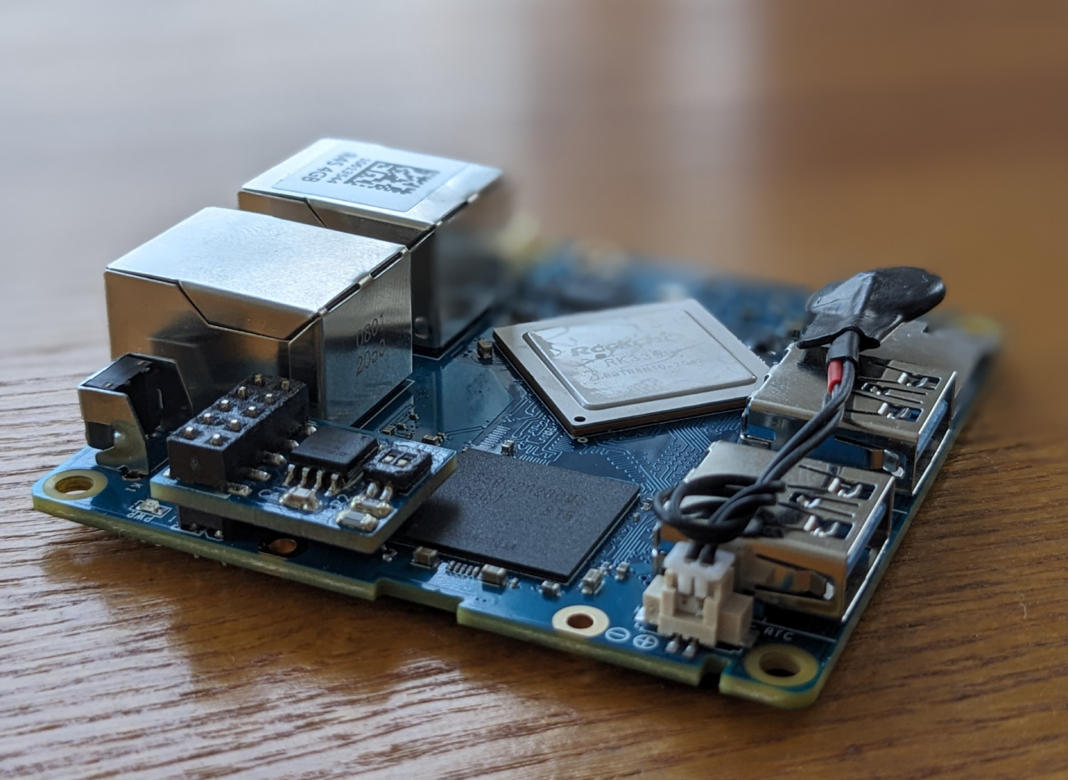
So when I was researching my options I noticed that the GPIO header on the board exposes SPI1 which just so happens to be the first location the RK3399 tries to load the bootloader from. If only I can get a NOR flash chip attached to this header, I might just be a little bit happier when using this SBC.
PCB Design
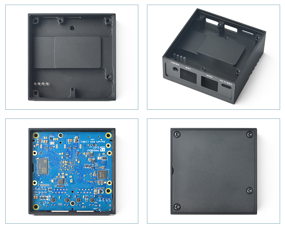
I'm no electrical engineer but I have dabbled with microcontrollers in the past and I have played with designing a PCB exactly once before many years ago so I was pretty clueless going into this. As an extra challenge it had to be quite compact as I have the aluminum case that everything needs to fit into, which doesn't allow for much room.
The PCB is 66x66mm (66mm == 2.598425 inches) for reference.
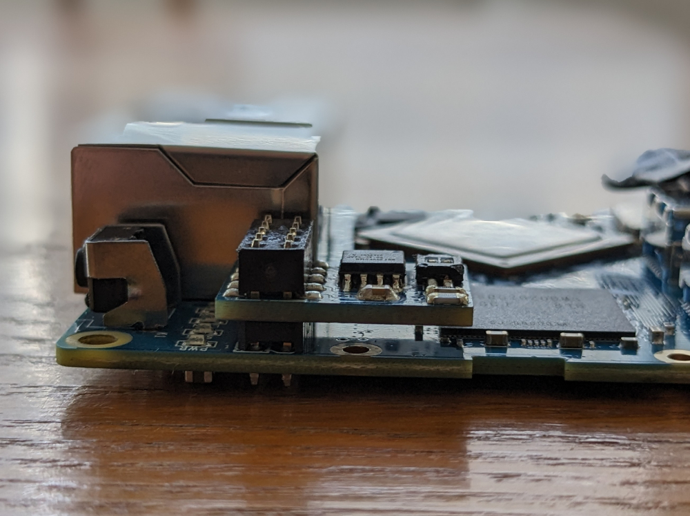
Thankfully, there is a bit of a raised section in the big heatsink chunk of the case that touches the CPU (through a thermal pad). This section is on the left side of the pictures (above the light tubes) and it just tall enough to get a PCB (with relatively thin components on it) in there. The issue would be to mount the PCB low enough without having to solder it to the headers on the SBC.
Normal female pin headers mount on top of the pin headers of the SBC (think of a Raspberry PI hat) which would be way too tall to be able to then close the case again but then I discovered these cool bottom mountable pin headers from Harwin called M20-7810545.

Look how low profile that is!
When it comes to the actual schematic and PCB design, there's not much to it. Just the NOR flash chip itself, a decoupling capacitor and a dip switch for enabling write protection and hold functionality, along with some pull-up resistors. I have released the kicad project files and gerbers on GitHub.
Note that a previous revision included an i2c EEPROM for storing mac addresses for the different ethernet interfaces, but ended up just storing this in the U-Boot environment instead.
Back to Tow-Boot
Now we have added a NOR flash chip to SPI1 but the config for this board in U-Boot doesn't include any support for a NOR flash and even worse, there isn't even any support for this board in Tow-Boot!
The latter is very easily added as all board definitions in Tow-Boot are defined in nix and there were previous boards supported with RK3399 that I could look at for reference. I have opened a pull request
in order to get this added upstream which has been merged and will most likely be available in the next release after 2023.07-007. This does not include support for my SPI flash module. This I have in a custom Tow-Boot build repository
as I think this can't be easily upstreamed.
So the installation to the SPI flash involves:
- Checkout my custom Tow-Boot build.
- Run
nix-build -A friendlyElec-nanoPiR4S-SPI(nix install instructions not included). - Burn the resulting
./result/spi.installer.imgto an SD card (dd if=./result/spi.installer.img of=/dev/sdX bs=1M oflag=direct,sync status=progress). - Boot from the SD card while attached to the serial port header on the NanoPI R4S and there should be presented to you the option to erase and flash the SPI NOR flash.
Alternatively you can download the pre-built
spi.installer.imgfrom the GitHub release in my repository.
Persistent MAC addresses
U-Boot has its own device tree for the device compiled and included with the bootloader. It will load this device tree during startup and patch it with values from env variables ethaddr
and eth1addr
into the MAC addresses for the different ethernet interfaces. With the NOR flash the environment can be changed and saved between reboots.
Use the following commands in the U-Boot console to set yours:
env set -f ethaddr aa:bb:cc:dd:ee:ff
env set -f eth1addr aa:bb:cc:dd:ee:fe
env save
Bonus sanity: RTC
Another annoyance of many SBCs is the lack of an RTC (Real Time Clock) which means that until an internet connection is established and the NTP client has fetched the correct time from a NTP server the system time is very wrong. This can happen rather late in the boot process.
The NanoPI R4S does include an RTC and a small header to include a battery for keeping time when powered off but, again, due to space constraints not even a CR2016 coin cell battery fits inside the case. I did however manage to fit a CR1216 by soldering wires directly to the battery (generally not recommended, the correct approach is to spot weld to them) and put heatshrink around it. It can then rest on top of the SD card slot and the case be closed. Enjoy your real time during bootup!
Discuss on Hacker News or Reddit
